Signal edge detection
This article was originally published on x-engineer.org
Thanks to x-engineers for their contribution.
--
Signal edge detection is a technique widely used in embedded software, model based development and electronics. A signal edge is defined as the transition of the signal from a high state to a low state or vice-versa. Depending on the type of transition, there are three different types of edge detection:
- rising edge: when the input signal is transitioning from a low state (e.g. 0) to a high state (e.g. 1)
- falling edge: when the input signal is transitioning from a high state (e.g. 1) to a low state (e.g. 0)
- either edge: when the input signal is changing state, from high to low or from low to high
Image: Signal edge detection
The detection of the edge is done on discrete signals. The edge detection is represented by an output Boolean signal, which has the value 1 (true) only during a time step, when the state change has occurred,
Signal edge detection is useful in for timers, counters or clock resets, for signal state updates or for triggering a set of functions / algorithms.
Rising edge detection
A rising edge is the transition of a signal from a low state to a high state. In Xcos, for a discrete signal, this transition can be detected by comparing the actual value of the signal u[k] with the previous value u[k-1].
Image: Xcos model – rising edge detection
In the Xcos block diagram above, Sig_Dec represents the input signal, which is changing state. The Delay block has the Discretization time step set to 0.001 s. This means that the output of the Delay block will be delayed with 1 ms. If the current value of the signal is bigger than the value it had 1 ms ago, a rising edge had occurred. The RisngEdge_B output signal will be a Boolean pulse signal for the edge detection.
Falling edge detection
The falling edge detection is done in a similar manner as the rising edge. The only difference is that we check if the current value of the signal is lower than the value it had one time step before.
Image: Xcos model – falling edge detection
Either edge detection
An either edge detection looks after both rising or falling edges. If any of them occurs, the Boolean output is set to true only during the state transition time step.
Image: Xcos model – either edge detection
The easiest way to implement an either edge is by performing a logical OR between the rising edge and falling edge detection.
To test the signal edge detection we are going to use square wave defined with a Pulse Generator block from the Xcos palette. The parameters of the signal are:
- Phase delay (secs):
0 - Pulse Width (% of period):
50 - Period (secs):
2 - Amplitude:
1
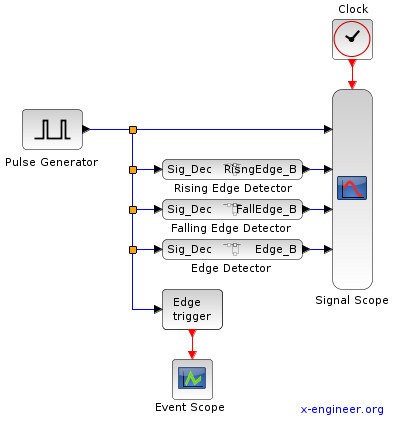
The output of the signal generator is fed to the signal edge detection functions described above. The shape of the square wave and the outputs of the edge detection subsystems are then plotted in a Scope block, triggered at 0.001 s.
Image: Xcos model – pulse edge detection
Running the model for 6 s outputs the following graphical window:
Image: Pulse edge detection output
The first, upper signal plot is the input square wave. The second plot contains the rising edge detection, the third plot is the falling edge detection and the fourth plot is the either edge detection. For a better visualization, the Delayblock has the parameter Discretization time step set to 0.1 s, which makes the Boolean edge detection signals to be true for 100 ms. As you can see, the either edge is contains both rising and falling edge detection.
Edge detection can be performed also with the Xcos block Edge trigger. Every time there is a state change in the input signal (rising or falling), the block will output an event. This can be used to trigger other discrete Xcos blocks. In our example we use a Event Scope block to plot the occurrence of the edge detection events.
Image: Edge detection event
As you can see the edge detection events occur in the same time with the edge detection pulses.
Edge detection application example
We can use edge detection to update the value / state of a signal. In the following example, we’ll use both the edge detection pulses and events, to sample/update a signal with the values of a sine wave. We expect to have the same results for both methods (edge pulse and event).
Image: Edge detection (signal and event) example
Having a time period of 2 s and a duty cycle of 50 %, the Pulse generator block will produce a square wave which will change state every 1 s. The either edge detection subsystem will generate a 1 ms pulse (set by the Delay block), which will update the value of the signal after the Dynamic switch block. When the edge pulse is 0 (flase), the output of the switch will be the previous value of the signal.
The edge detection mechanism will sample the sine wave every 1 s. The same behavior is obtained using the Edge trigger block. At every edge detection an event is generated which will trigger the Sample and Hold block.
The outputs of both sampling methods (edge detection pulse and event) are fed in a Scope block (updated every 1 ms).
Image: Edge detection (signal and event) example plot
The upper plot represents the edge detection pulse. The middle contains the sine wave and its sampling with the Dynamic switch. The lower plot contains the sine wave and its update based on the Sample and Hold edge event trigger. As you can see, both methods produce the same result.
This edge detection mechanism will be used to reset a timer, but this is the topic of another Xcos tutorial.


